一、summarize
DLML1 series leakage circuit breakers (hereinafter referred to as leakage breakers) are one of the new types of circuit breakers that have been designed and developed by the company using international advanced technology. Suitable for leakage protection in AC 50/60Hz, rated operating voltage up to 400V, rated operating current from 16A to 630A in the distribution network circuit, it can also prevent the fire hazard caused by ground fault current due to equipment insulation damage. Can be used to allocate power and protect the line and power supply equipment from overload, short circuit and other damage, can also be used as the motor's infrequent start and overload, short circuit protection.
The leakage circuit breaker has the characteristics of small volume (the same volume of the corresponding molded case circuit breaker), high breaking, short arcing, and adjustable residual operating current, and can also be provided with an alarm contact, a shunt release, and an auxiliary touch. First-class accessories are ideal for users.
Leakage circuit breakers are installed vertically (ie, vertically) and can also be installed horizontally (ie, horizontally).
This product complies with GB6829idtIEC60755. GB14048.2idtIEC60947-2 standard.
二、model and its meaning
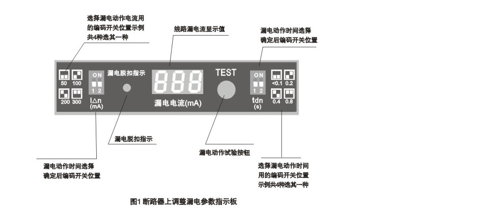
三、functional characteristics
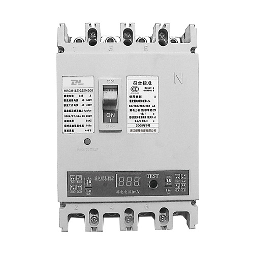
Leakage current I △ n (adjustable): (30) 50mA-500mA.
Leakage action time (adjustable): non-delay <0.1s, delay 0.2s/0.4s/0.8s (1s).
Digital display actual leakage current.
Earth leakage trip indication: light emitting diodes.
Leakage alarm and trip function:
1 Trip after alarm - The alarm starts when the leakage current reaches 0.65I △ n ± 10%, and the tripping action occurs when the leakage current reaches 0.8 I △ n ± 10%.
2 alarms do not trip - alarm when the electric current reaches I △ n ± 10%, but cannot trip.
3 alarm form - the sound signal of the buzzer in the circuit breaker.
- External use special auxiliary contact action (contact capacity AC220V, 1A)
四、classification
|
3.1Divided by the number of poles
|
3.2According to the mode of operation
|
3.3According to the wiring method
|
3.4According to rated leakage action time
|
3.5Overcurrent release type
|
|
Quadrupole(4P)
|
Handle directly
|
Board wiring
|
Delay type (adjustable)
|
Instantaneous trip type
|
|
Three-pole four-wire(3N)
|
Electric mechanism operation
|
Post-board wiring
|
Non-delay(<0.1s)
|
Duplex trip type
|
|
|
Turn handle operation
|
|
|
|
|
accessory name/
Attachment code /
Overcurrent tripping
|
Without accessories
|
Alarm contact
|
Shunt release
|
Auxiliary contact
|
Undervoltage release
|
|
Instantaneous release
|
200
|
208
|
210
|
220
|
230
|
|
Duplex release
|
300
|
308
|
310
|
320
|
330
|
五、Normal use conditions
4.1 Ambient air temperature
4.1.1 The upper limit of ambient air temperature is +40°C;
4.1.2 The lower limit of ambient air temperature is -5°C;
4.1.3 The average ambient air temperature 24h does not exceed +35 °C;
4.2 Altitude: The altitude of the installation site does not exceed 2000m.
4.3 Pollution Level: 3.
4.4 Installation Category: III
4.5 Atmospheric conditions: Atmospheric relative humidity does not exceed 50% at ambient air temperature of +40°C; higher relative humidity may be obtained at lower temperatures; monthly average maximum relative humidity of the wetest month is 90%, and the month The monthly average minimum temperature is +25°C and takes into account the condensation that occurs on the surface of the product due to temperature changes.
4.6 External magnetic field: The external magnetic field near the place where the leakage breaker is installed shall not exceed 5 times of the geomagnetic field in any direction.
六、main technical parameters
6.1 Rated value of leakage circuit breaker
|
Type
|
Frame rated current Inm(A)
|
Rated current In(A)
|
Rated operating voltage Un(V
|
Number of poles
|
Rated residual operating current
I△n(mA)
|
Rated residual non-operating current
I△n(mA)
|
Rated limit short-circuit breaking capacity Icu(KA)
|
Rated operation short circuit breaking capacity Ics(KA)
|
Arc distance(mm)
|
|
DLML1-100
|
100
|
16、20、25、32、40、50、63、80、100
|
400
|
3、4、3N
|
30、50、100、200、300、500
|
15、25、50、100、150、250
|
30
|
15
|
≤50
|
|
DLML1-225
|
225
|
100、125、160、180、200、225
|
400
|
3、4、3N
|
50、100、200、300、500
|
25、、50、100、150、250
|
30
|
15
|
≤50
|
|
DLML1-400
|
400
|
225、250、315、350、400
|
400
|
3、4、3N
|
100、200、300、500
|
50、100、150、250
|
50
|
25
|
≤100
|
|
DLML1-630
|
630
|
400、500、630
|
400
|
3、4、3N
|
100、200、300、500、1000
|
50、100、150、250、500
|
65
|
40
|
≤100
|
|
DLML1-800
|
800
|
700、800
|
|
3、4、3N
|
100、200、300、500、1000
|
50、100、150、250、500
|
65
|
40
|
≤100
|
Note: The remaining operating current of the fourth gear can be arbitrarily selected by the user.
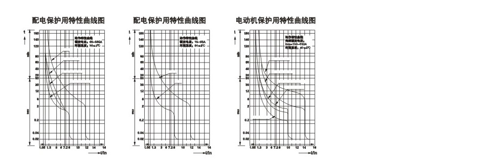
6.2 Inverse Time Offset Characteristics of Current-Exciting Circuit Breaker Overcurrent Breaker
|
NO.
|
Test current name
|
I/In
|
Appointment time
|
Starting state
|
|
1
|
Agreement does not trip current
|
1.05
|
2h(In>63A),1h(In≤63A)
|
Cold
|
|
2
|
Agreed tripping current
|
1.30
|
2h(In>63A),1h(In≤63A)
|
Immediately after the first trial
|
6.3 Inverse time limit of the current leakage protection circuit breaker for overcurrent protection of motor protection
|
NO.
|
Setting current
|
Appointment time
|
Starting state
|
|
Inm=100A
|
Inm=225A、400A
|
Inm=630A
|
|
1
|
1.05In
|
>2h
|
>2h
|
>2h
|
Cold
|
|
2
|
1.2In
|
≤2h
|
≤2h
|
≤2h
|
Immediately after the first trial
|
|
3
|
1.5In
|
≤4min
|
≤4min
|
≤8min
|
Hot
|
|
4
|
7.2In
|
T≥1s
|
4s<T≤10s
|
6s<T≤20s
|
Cold
|
6.4 Residual current breaking time of leakage breaker.
6.4.1 Residual current breaking time of general earth leakage circuit breaker
|
Leakage current
|
I△n
|
2I△n
|
5I△n1)
|
10I△n2)
|
|
Non-delayed
|
Maximum disconnection time(s)
|
0.2
|
0.1
|
0.01
|
0.04
|
|
Delay type
|
Maximum disconnection time(s)
|
0.7/1.2/2.2
|
0.6/1/2
|
0.5/0.9/2
|
0.5/0.9/2
|
|
Limit inoperative time(s)
|
-
|
0.2/0.4/0.8
|
-
|
-
|
Note: 1) Use 0.25A instead of 5I △n for an earth leakage circuit breaker with I△n ≤ 30mA.
2) For leakage circuit breakers with IΔn > 30mA, substitute 0.5A for 10IΔn.
3) If the user needs special current leakage current specifications, please indicate when ordering or design drawings.
6.5 Leakage Circuit Breaker Inverse Time Protection Characteristic Curve
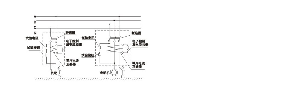
七、structure and working principle
7.1 This series of residual current circuit breakers are electronic residual current circuit breakers. They are mainly composed of zero sequence transformers, electronically controlled leakage releases and circuit breakers with overload and short circuit protection. All components are installed in a pair of plastic housings. .
7.2 When there is a leakage or personal electric shock in the protected circuit, as long as the residual current reaches the setting action current value, the output signal of the secondary winding of the zero-sequence transformer triggers the conduction of the thyristor and makes it through the leakage release. Leakage circuit breakers act to shut off the power supply for leakage and electric shock protection. Working principle (see figure)
7.3 When the circuit to be protected is overloaded or short-circuited, the multi-function trip unit completes the delay or instantaneous tripping action to activate the leakage circuit breaker, thereby cutting off the overload or short circuit protection of the power supply.
7.4, use and maintenance
The long-delay and short-circuit protection characteristics of the circuit breaker are set by the manufacturer, and the user should not adjust it arbitrarily due to no special adjustment of the equipment.
When the main circuit is powered on, press the “Test” button. This test procedure only proves that the circuit breaker itself is normal, but it cannot indicate the specific current and time of the leakage current. (Use the test button 3 times, it should operate correctly, with load switch 3 times, there should be no malfunction). Circuit-breakers fitted with undervoltage disconnectors must be energized first. Circuit breakers can be buckled and closed again. Otherwise damage switch!
If personal safety is directly protected by a circuit breaker, the leakage current should be selected as I △ n ≤ 30 mA (for some humid, medical applications, I △ n = 10 mA is not produced by the factory).
Tests for withstand voltage tests and insulation resistances can only be made between relative grounds. The above test cannot be performed between phases because of the presence of electronic components in the product.
The leakage circuit breaker is marked with the power supply side (Example 1.3.5) and the load side (Example 2.4.6). The wiring must be installed as specified and cannot be poured into the line. Because the inverted line will burn out electronic components when the leakage action occurs.
Three-phase load imbalance should be controlled within 25%.
Check the insulation resistance of the low-voltage network to the ground before installation.
The electrician should check the leakage protection function with the “test button” periodically (eg 1 month). It is strictly forbidden to use the phase line to make direct contact with the zero line to do the motion check.
Electricians should conduct inspections on a regular basis, timely detect operational failures, and deal with them in a timely manner.
If a newly installed circuit breaker is found to be “false jump”, it should be checked in time for repeated grounding or unacceptable grounding resistance or incorrect wiring, phase-neutral wire reversal, and so on.
When the user observes the conditions of storage and use, from the date of shipment from the factory, no more than 18 months, the seal is in good condition. If it is a factory quality problem, the factory is responsible for replacement or repair.
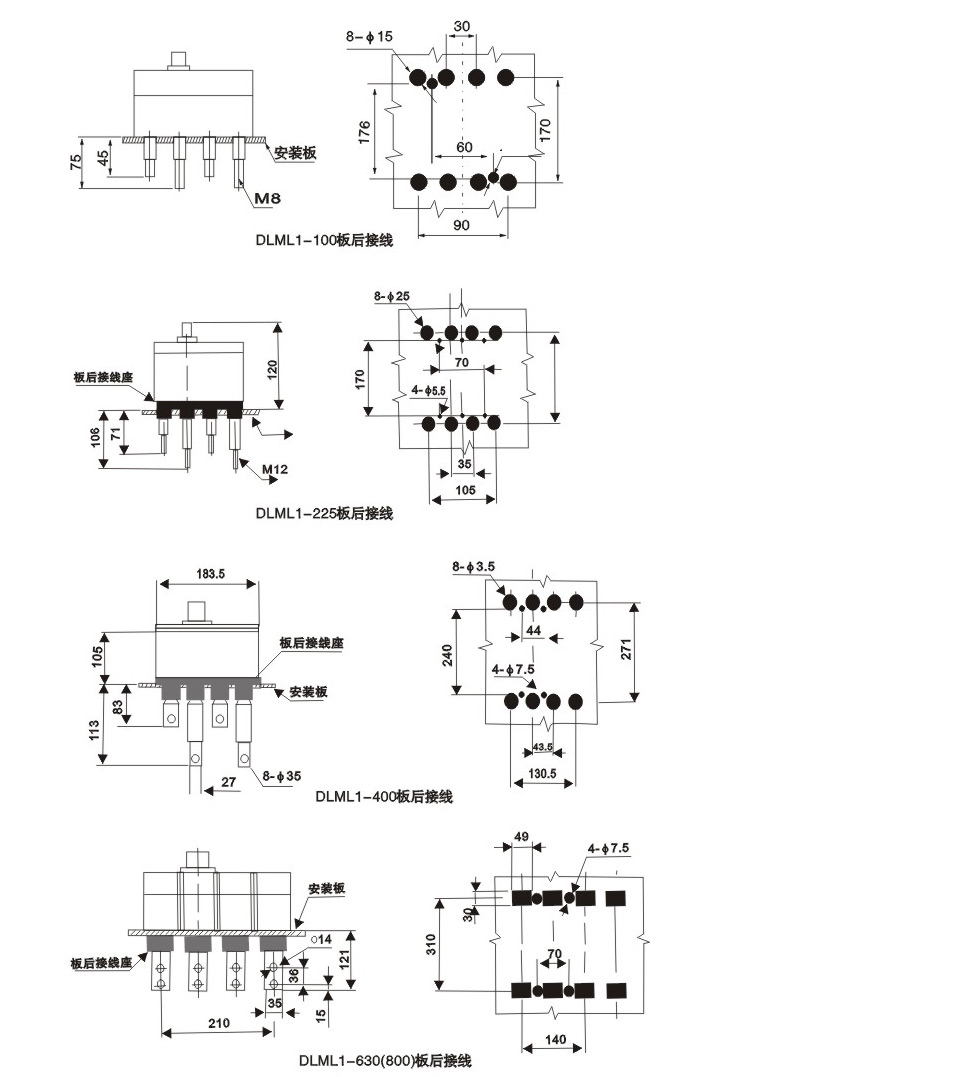
八、shape and installation size
|
Type
|
Frame rated current(A)
|
Number of poles
|
|
Installation size
|
|
A
|
B
|
D
|
a
|
b
|
Φd
|
|
DLML1-100
|
100
|
3
|
90.5
|
195
|
110
|
20±0.14
|
167±032
|
2-φ5+0.32 0
|
|
4
|
120
|
195
|
86.5
|
60±0.20
|
167±032
|
4-φ5+0.32 0
|
|
3N
|
120
|
155.5
|
86.5
|
60±0.20
|
167±032
|
4-φ5+0.32 0
|
|
DLML1-225
|
225
|
3
|
105
|
213
|
110
|
35±0.16
|
170±032
|
4-φ5+0.32 0
|
|
4
|
140
|
213
|
110
|
70±0.23
|
170±032
|
4-φ5+0.32 0
|
|
3N
|
140
|
213
|
110
|
70±0.23
|
170±032
|
4-φ5+0.32 0
|
|
DLML1-400
|
400
|
4
|
182.5
|
303
|
155
|
44±0.26
|
240±043
|
4-φ7+0.33 0
|
|
3N
|
183.5
|
303
|
155
|
44±0.26
|
240±043
|
4-φ7+0.33 0
|
|
DLML1-630
|
630
|
4
|
280
|
342
|
155
|
70±0.23
|
310±043
|
4-φ7+0.33 0
|
|
3N
|
280
|
342
|
155
|
70±0.23
|
310±043
|
4-φ7+0.33 0
|
|
DLML1-800
|
800
|
4
|
342
|
342
|
155
|
70±0.23
|
310±043
|
4-φ7+0.33 0
|
|
3N
|
342
|
342
|
155
|
70±0.23
|
310±043
|
4-φ7+0.33 0
|
九、selection principle
9.1 When selecting the rated residual operating current value of the leakage breaker, the normal leakage current value of the protected circuit and equipment shall be fully taken into account. If necessary, the leakage current value of the protected circuit or equipment may be obtained through actual measurement.
9.2. The rated residual operating current of the residual current circuit breaker shall not be less than 2 times the maximum value of the normal leakage current of the electrical circuit and equipment.
9.3. For hand-held power tools, mobile electric appliances, household appliances, sockets, and construction site electrical appliances (rated current of not less than 100A) and other equipment grounding difficulties, the residual current breakers with a rated residual operating current of 30mA or less should be preferred.
9.4 Single earth leakage circuit breakers with a rated residual operating current of 3 mA or less may be used for a single device. The total protection of multiple devices (multi-branch) should use residual current circuit breakers with rated residual operating current of 30mA or more.
9.5、Electrical equipment installed in a wet place should use a residual current circuit breaker with a rated residual operating current of 30mA or less.
十、ordering instructions
The user must specify when ordering:
10.1 Type and name of leakage circuit breaker;
10.2 Rated current of an overcurrent release of an earth leakage circuit breaker;
10.3 Rated residual operating current of leakage breakers;
10.4 Breaking time of leakage breaker;
10.5. Types of protection, number of poles, and quantities;
10.6 Rated voltage of internal leakage breaker accessories and external accessories.
For example: order DLML1-100P/3310 leakage circuit breaker, overcurrent release rated current 40A, rated
Residual operating current 30/50/100mA (adjustable in third gear), breaking time <0.2s,
3-pole with shunt release (AC230V), electric operating mechanism (AC230V), for distribution protection, quantity
10 equipment.