一、summarize
OLQ3-63 series automatic switch electrical appliances. (referred to as ATSE) electrical level CB level, to our company DL-63, small Circuit breaker as an actuator.
This product complies with GB/T1448.11-2002 "Low-voltage switchgear and control equipment - Part 6: Multifunction appliances: Part 1: Automatic transfer switch electrical appliances", equivalent to using lEC60947-6-1998 "Low-voltage switchgear and control equipment No.6 Part: Many Functional Appliances Part 1: Automatic Transfer Switching Appliances), Compliance (Fire Protection Codes for High-Rise Civil Buildings), Fire Protection Codes for Architectural Design,
Design Guidelines for Interest-Bearing Lighting, and Design Codes for Civil Electrical Installations.
二、scope of application
Suitable for dual-supply power supply systems with 50Hz text, rated operating voltage of 400V and rated current up to 63A.The automatic conversion between the power supply (QN) and the backup power supply (QR) ensures the reliability and safety of the power supply. Widely used in hospitals, shopping malls, banks, chemical, high-rise buildings, military facilities and other important places that do not allow power off.
三、product characteristics
A) It has a double protection of reliable mechanical interlocking and electrical interlocking.
B) With undervoltage, phase failure automatic switching function.
c) The delay time is externally adjustable and can be adjusted by the user.
d) Energy saving, no vocal operation.
e) Compact, safe and easy to use.
f) The appearance is beautiful and novel, and the surface adopts advanced electrostatic powder coating technology. The coating is characterized by strong corrosion resistance and good strength.
g) High degree of product standardization. Universality. The three-pole, four-pole automatic transfer switch has uniform dimensions and installation dimensions.
Can be user-friendly design and selection.
四、normal working conditions and installation conditions
4.1 Ambient air temperature:
The ambient air temperature upper limit does not exceed +40°C; the lower limit does not exceed -5°C and the 24 hour average does not exceed +35°C.
4.2 Elevation:
The altitude of the installation site is generally not more than 2000m.
4.3 Atmospheric conditions:
The relative humidity of the air at the installation site does not exceed 50% when the maximum ambient air temperature is +40°C.
To have a higher humidity; in the lowest monthly average temperature of +2O °C in the wettest month, the relative humidity can reach 90%, and due to the condensation due to temperature changes should take appropriate measures to prevent.
4.4 Usage Category:
AC-33B. (Infrequent operation, typical use for motor load or motor, resistance load and 30% or less white
Incandescent load of mixed load).
4.5 electrical level: level.
4.6 Pollution Level 2.
4.7 Installation Category:
Main circuit installation category II, III. Control and auxiliary circuit installation category II.
五、model meaning
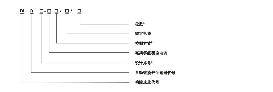
Note: 1) Number of poles: 3, 4 and 4;
2) Control-side mode: Grid-electric grid Normal type: default, self-recovery;
3) Design number: 3 breaking capacity 4.5KA, 3H breaking capacity 10KA (intelligent), 3M breaking capacity 10KA (economy)
六、main technical parameters
|
Type
|
DLQ3-63
|
|
Number of poles
|
3、4
|
|
Rated worker current leA
|
6、10、16、20、25、32、40、50、63
|
|
Rated short-circuit breaking capacity cs breaking current KA
|
6
|
|
Rated operating voltage Ue V/AC
|
400
|
|
Rated frequency Hz
|
50
|
|
Rated insulation voltage Ui V
|
690
|
|
Undervoltage switch value
|
70% Ue
|
|
Return value after return
|
85% Ue
|
|
Switching delay Tn S
|
1-10±2
|
|
Return delay Tn S
|
1-10±2
|
|
Control voltage range
|
85%Ue-110%Ue
|
|
Power operation cycles
|
1000
|
|
No power cycle
|
5000
|
|
Contact conversion time S
|
≤2
|
七、Working principle and function design
The main structure of ATSE is composed of a controller, a mechanical interlocking mechanism and two miniature circuit breakers. Two power supplies are provided by the control side Depression state. According to the male to send a signal to the motor, the motor drives the mechanical interlocking mechanism to operate the two circuit breakers. On the panel
Two electric deep working status indications and two circuit breaker load status indications. All components are mounted on a metal plate and installed A connection terminal on the board is used to transfer the indication on the panel to the panel of the electrical control box. Make it easy for the user to observe
Switch working state. With undervoltage, phase protection.
1, the controller panel
The toggle switch on the controller panel can be used for automatic and manual state transitions and two time delay potentiometers (Tn, Tr)
Delay time can be adjusted. Tn is the conversion delay time and Tr is the return delay time.
Four light emitting diodes on the opposite side of the controller face indicate the normal, standby power and switch closing positions, respectively.
|
Common power supply
|
backup power
|
Control status
|
Display state
|
|
Un
|
Ur
|
Qn
|
Qr
|
|
normal
|
normal
|
Common power supply:QFN close,QFR separate
|
+
|
+
|
+
|
-
|
|
normal
|
abnormal
|
Common power supply:QFN close,QFR separate
|
+
|
+
|
+
|
-
|
|
abnormal
|
normal
|
Common power supply:QFN separate,QFR close
|
+
|
+
|
-
|
+
|
|
Back to normal
|
normal
|
Common power supply:QFN separate,QFR close
|
+
|
+
|
+
|
-
|
Note: QFN - Miniature Circuit Breaker Controlling Common Power Supply QFR - Miniature Circuit Breaker Controlling Backup Power Supply
Un-common power indicator (red) Ur-standby power indicator (red)
Qn-common power supply is connected (green) Qr- standby power supply is connected (green)
+ A light is on - The light is off
2, controller monitoring and control functions
ATSE is used to convert between common and standby power supplies. The controller detects real-time three-phase power and standby power Ll. When the normal power supply voltage is normal, the switch is placed in the "automatic" position, the backup circuit breaker is divided, and the common circuit breaker is closed. To ensure that the common power supply is connected to the load. When the common power supply drops below 70% Ue or all the voltages of one or three phases of the common power supply are interrupted, the common power supply is switched to the standby power supply (when the standby power supply is normal) through the set conversion delay, and the common power supply is restored to When normal, the standby power is returned to the common power supply by the return delay.
Note: The terminal has been connected to 220V power supply, users do not need to join the power supply. Please disconnect the power when operating.
八、operation mode
1. The automatic operation will pull the switch to the automatic position, and the switch will enter the automatic working state. In the automatic state, it is forbidden to use the handle for manual operation.
2. The manual operation will pull the switch to the manual position. Rotate the operation handle to make the extension handles of the two miniature circuit breakers move back and forth to make the circuit breaker split and close. Flexible, reliable and stable, the manual conversion of the two power supplies can be completed. The two circuit breakers cannot be in the closed state at the same time, but they can be in the split door state at the same time.
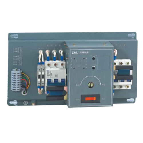
九、 shape and installation size
Product appearance see circle 1, circle 2, size and size of the split controller see decline 1, circle 3, circle 4, table 2
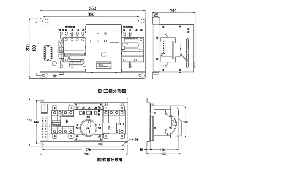
|
Frame level current(A)
|
Controller type
|
size(mm)
|
Installation size(mm)
|
|
L
|
W
|
H
|
L
|
W
|
Mounting hole diameter
|
|
63
|
3
|
350
|
200
|
144
|
320
|
180
|
Φ6.5
|
|
3
|
290
|
160
|
122
|
270
|
148
|
Φ6
|
十、 electrical wiring diagram shown in Figure 3, Figure 4
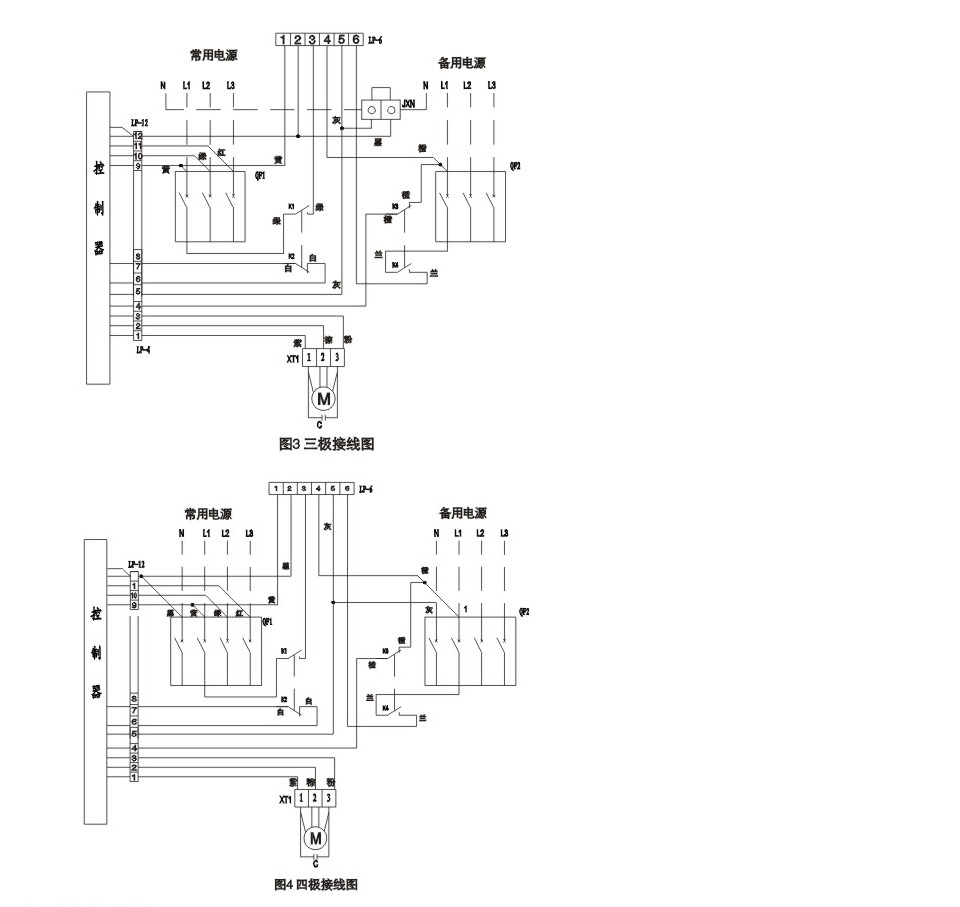
Note: The virtual level is user wiring
QFI, QFZ miniature circuit breaker; M motor;
K1, K2, K3, K4 motion switches; C capacitance
XT1, XT2 terminal block; L1, L2, L3 phase power
N Neutral; JXN Three-pole N-terminal row;
Lp-6, LP-12 connector
十一、Preparation and precautions before putting into use
1, installation
In order to ensure your personal safety and electrical equipment safety. Before ATSE is put into operation, users must do:
1) The instruction manual must be read carefully before installing ATSE.
2) ATSE must be put into use under normal working conditions.
3) Before installation, check whether the ATSE circuit breaker's specifications meet the requirements of the use;
4) Measure the insulation resistance of the main circuit with a 500V megger before and after installation (please note: the secondary circuit must be disconnected, otherwise the controller will be damaged), at an ambient temperature of 20°C, 5°C and 50%-70% relative humidity. Should not be less than 10M. Otherwise, the circuit breaker must be dried and used only after the insulation resistance reaches the specified requirements.
5) Fix the ATSE according to the mounting dimensions and dimensions shown in Figure 1. Connect the guide according to Figure 2 or Figure 3
The additional stress shall be applied to the circuit breaker. According to the rated current, the guide section of the corresponding specification shall be selected. The N-class and grounding wire shall be correct, reliable and firm. The user can connect the terminals on the mounting board with the external indicator light according to the need of the connection coil 4 .
6) After the product is installed. The conductor cross section that meets the standard should be selected according to the size of the rated current. For quadruple ATSE, the N line cannot be miswired, otherwise the controller and motor operating mechanism will be burned. For the three-level ATSE, an additional N-pole is required on the N terminal of the ATSE.
7) The grounding of the bottom plate must be reliable.
8) If the ATSE power frequency withstand test is required, disconnect the controller's LP-12 connector.
2, debugging
Before debugging. Carefully check that the wiring is correct. After the determination, the following adjustments can be made:
1) Mechanical interlock debugging
Press nibby to the manual position, rotate the operating handle to make the extension handles of the two miniature circuit breakers move back and forth to make the circuit breakers split and close. The action must be flexible, reliable and smooth. The two breakers cannot be in the closing state at the same time, but they can be in the open state at the same time.
2) Ordinary tank controller debugging
1 Switch on the common power supply and standby power supply, and the indicator lights of Un and Ur lights up. Explain that the common power supply and standby power supply are connected;
2 press niu according to the automatic position, then the ATSE enters the automatic control state. Under the normal power supply normal state, the motor will turn to make the circuit breaker of the common power supply of the control side close, and at this time, the common power supply supplies the load;
3 When the commonly used power switch is connected to the negative switch, standby power is normal. Un, Ur, On light is on.
4 When the common power supply fails and the standby power supply is normal, the ATSE is set to convert the load from the normal power supply to the standby power supply, and the Un, Ur, Qr indicator lights (L1 phase uninterrupted), and the standby power supply is in operation; V. When the common power supply returns to normal, the ATSE automatically resets the negative wear to the common power supply after the delay is set.
5 Users can adjust the potentiometer Tn, Tr according to need to determine the conversion delay time and return delay time.
Note: Do not use the controller in the automatic state.
3, special circumstances debugging
1) When both the normal power supply and backup power supply are powered off or fail at the same time. Press the button to the manual position, and turn the handle so that the switches QFN and QFR are opened at the same time.
2) When the load is short-circuited or overloaded, the circuit breaker is opened. After pressing the button to the manual position, turn the handle to the opening position. Only after the load failure is removed, can it be operated.
十二、Common Faults and Solutions See the table below
|
No.
|
Common fault conditions
|
main reason
|
General treatment method
|
|
1
|
Switch does not work after power is turned on
|
Case 1: Indicator light is on
a) The potentiometers Tn and Tr are in the maximum position.
b) It can work normally after delay.
|
The controller panel indicates the direction adjustment potentiometer. Make it ideal to switch
|
|
c) button is in manual position
|
Make button in automatic position
|
|
Case 2: The indicator is off
a) N line connection is not, b) reliable, c) virtual connection
|
Make N line reliable connection
|
|
D) The controller's fuse tube is blown or has poor contact.
|
Reinstall the fuse or replace the fuse.
|
|
f) The button is in the manual position.
|
Make button in automatic position
|
|
2
|
After the power supply is connected, the normal power supply is normal, and the switch works in the standby power position.
|
a) The wiring at the incoming end of the common power supply is not reliable.
|
Make the wiring of the common power supply terminal securely.
|
|
b) The controller's fuse tube is blown or has poor contact.
|
Reinstall the fuse or replace the fuse.
|
|
c) The button is in the manual position.
|
Make button in automatic position
|
|
3
|
Common power supply is abnormal, standby power is normal, and the switch does not switch to standby power
|
a) The wiring of the backup power supply is not reliable
|
Make sure that the backup power supply terminal is securely wired.
|
|
b) The controller's fuse tube is blown or has poor contact.
|
Reinstall the fuse or replace the fuse.
|
|
c) The button is in the manual position.
|
Make button in automatic position
|
|
4
|
Leakage phenomenon
|
Unreliable grounding Tighten the ground screw
|
|
十三、 On-site maintenance and repair
When the ATSE overhauls or periodically checks, put the controller in the "manual" state to debug it.
The controller cannot be plugged and plugged. When checking the various arrays, make sure that the power supply has been removed and pay special attention to personal safety!
When a circuit breaker trips automatically, the function on the controller must be switched to the manual state to check the line fault. After the fault is removed, the circuit breaker can be switched to the automatic state to close the circuit breaker.
Products that are not used for a long period of time should be protected against moisture and dust, and they should be commissioned as described above before use, and they can be put into operation after normal operation.
This product is guaranteed for one year from the date of delivery. During the warranty period, the user adjusts, uses, and maintains the product according to the requirements of the product. However, if the product itself cannot be used due to quality problems, the factory is responsible for repairs, replacements, and returns.
十四、selected ATSE products should be noted several wings
1. Pay attention to what standards the product meets.
At present, there are many ATSE products on the market and they are also confusing. ATSE must comply with GB/14048.11-2002.
In line with GB14048.3-2003 "switch, isolator, disconnector and fuse combination" products can only be called electric (or electrical operation) switch. Improper use of the user can easily cause a short circuit in the power supply system.
The automatic transfer switchgear is more stringent in accordance with GB/14048.11-2002. It is also allowed to switch directly between power supply phases.
2, pay attention to the use of products
As CB-class products have over-current protection devices, some places do not allow the use of CB-level ATSE (fireplaces to understand the "requires double-division" and "requires no over-current devices" option). There are also strict restrictions on the use of Class CB ATSE in the United States. Among them, UL1008 Clauses 41 and 19 stipulate that a switch with over-current trip must be presented to the user with a warning sign: "Warning - if the over-current fault causes the switch to open, the ATSE will not convert"
3, pay attention to the use of different categories
The use of switches indicates their ability to control the load. At present, there are many types of ATSE products on the market in China. ratio
Such as AC-38B, AC-31B, AC-3;
AC-33B/A*: Applicable motor hybrid load. Including motor, resistance load and incandescent lamp load below 30%, the on and breaking current is 6le, COSΦ=0.5;
AC-31B/A*: Suitable for non-inductive or micro-inductive load (resistive load), the connection and breaking current is 1.5Ie, COSΦ=0.8;
AC-3 cage induction motor starting, breaking during operation, should be connected to 10le / broken 8le, COS Φ = 0.45 (le greater than 100A is 0.35) requires the conversion test assessment.
Because ATSE is more difficult to pass the AC-33B test, some manufacturers reduce the switch usage requirements before choosing AC-31BUse categories. It is clear that the ATSE using the AC-33B is safer and more reliable than the AC-31B ATSE.
4, pay attention to the two-stage and three-stage different role
The two-stage ATSE switch main contact only has two working positions, which are both "usual power supply position" and "power standby position". The load will not have long-term power failure, and the power supply reliability is high, and the switching operation time is fast.
The three-stage ATSE switch main contact has three working positions and multiple “zero positions (refers to the electric state)”. The main contact is in the open position (neutral), and the load power-off time is relatively long. It is 2-3 times that of the two-stage power failure.
The three-stage “zero position” is mainly used for the ATSE to perform “transient stop” for the impulse-free current when the ATSE is switched with high-intensity or large-scale motor negative stages; it is not used for isolation when the load is maintained. . The use of isolation switch must be selected during maintenance, it is more secure.
Differentiating the meaning of the isolation function and the isolation switch, the use switch must have the following functions at the same time:
1 The movable contact can be locked or visible when in the off position;
2 has a higher weighted impact withstand voltage (1.25 times);
3 In any case, the limit leakage current should not exceed 6mA;
5, pay attention to the difference in time
General users should pay attention to "total action time" or "transition action time". To meet the requirements of different distribution systems.
Two-stage PC-class ATSE "total operating time" is generally 15ms~150ms.
Three-stage PC-class ATSE "total operating time" is generally 250ms to 600ms;
CB ATSE "total action time" is generally 2oooms ~ 3000ms.
When the artificial delay is set to a small value, it is beneficial to reduce the total operation time; when the time delay is set to a large value. It helps to avoid the short-time under-voltage and over-voltage conditions caused by equipment startup and grid interference, such as the short-term under-voltage that may occur when the motor is started (large-size fan, water pump, elevator); the high-voltage circuit breaker may trip after lightning. Short-term blackouts, etc. that occur automatically after reclosing.
6. Problems to be Concerned with High Inductive Load Switching Control
ATSE generally does not allow conversion with large motors or high inductance loads.
7, pay attention to the use of ambient temperature
With the maximum rated operating current, any temperature on the ATSE should not cause cross-forming or damage to the material. The temperature rise shall not exceed the specified position of 7.2.2 in GB 14048.1. This value is the maximum temperature rise allowed at ambient temperature +40°C.
Some manufacturers are free to change this parameter and have not been tested.
If the ambient air temperature is +55°C, the allowable maximum temperature rise should drop by 15K. If the terminal allows the maximum temperature rise from 7OK (silver or nickel) down 15K, that is 55K. The allowable absolute temperature of the terminal block is unchanged at 110°C. This temperature is related to external wires.
When the ambient temperature drops, the low temperature (-10°C to -25°C) may cause deformation of the material (insulation) and change of the performance of the thermal tripping port. Attention should be paid when using it.
The operating temperature of the coil of the electromagnet (pulse operation) is measured after operating continuously for 10 times at the rated operating frequency. The amount of resistance changes on the side. The temperature rise does not exceed the allowable temperature of the coil insulation.
Note: Due to changes in standard materials and technical requirements, the features described in the text and the images in this document are subject to confirmation by the technical department of the company. No changes will be notified beforehand.
十五、ordering instructions
1. Product model and name
2. Number of poles
Rated current
4. Order quantity