一、summarize
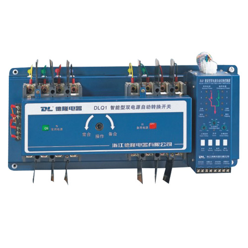
The DLQ1 series automatic transfer switch (ATSE for short) is a smart high-tech new product developed using new technologies. The circuit breaker is our company's DLM series molded case circuit breaker. Electrical level is CB level.
This product complies with GB/T14048.11-2002 "Low-voltage switchgear and control equipment - Part 6: Multifunction Electrical Part 1: Automatic transfer switchgear", equivalent to using IEC60947-6-1:1998 "Low-voltage switchgear and control equipment Part 6: Multifunctional Electrical Appliances Part 1: Automatic Transfer Switching Appliances, Compliance with Fire Codes for High-Rise Civil Buildings, Fire Protection Codes for Architectural Design, Emergency Lighting Design Guidelines, and Electrical Design Codes for Civil Buildings.
二、scope of application
It is suitable for dual power supply systems with AC 50Hz and rated working voltage of 400V. It can complete automatic conversion between common power supply (QN) and standby power supply (QR) to ensure the reliability and safety of power supply. Widely used in hospitals, shopping malls, banks, chemical, high-rise buildings, military facilities, fire and other important places that do not allow power off.
三、 normal working conditions and installation conditions
3.1. ambient air temperature: the upper limit of the ambient air temperature does not exceed +40 °C; the lower limit does not exceed -5 °C, and the average value of 24 hours does not exceed +35 °C.
3.2. Altitude: The elevation of the installation site is generally not more than 2000m.
3.3. Atmospheric conditions The relative humidity of the air at the installation site shall not exceed 50% at a maximum ambient air temperature of +40°C. It may have a relatively high humidity at a lower temperature; the average monthly minimum temperature is +20 in the wettest month. The relative humidity can be up to 90% at °C. Proper measures should be taken to prevent condensation due to temperature changes.
3.4. Use category: AC-33B. (Infrequent operation, typical load is motor load or mixed load including motor, resistive load and incandescent light load below 30%).
3.5, pollution level 3.
3.6. Installation category: Main circuit installation category III (power distribution level). Control and Auxiliary Circuit Installation Category II (Load Level)
四、model and meaning
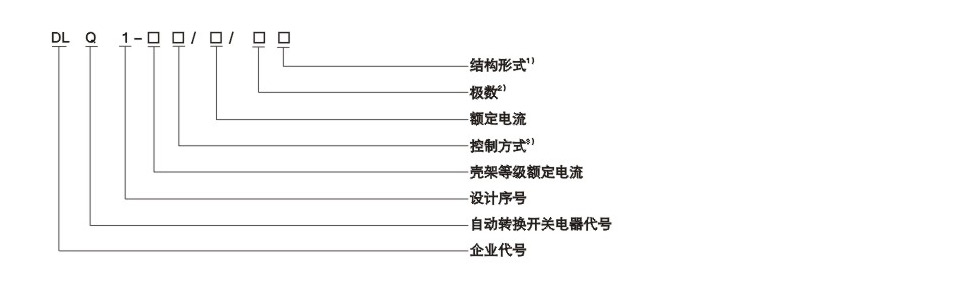
Note: 1) Structure: Z-integral, F-split;
2) Number of poles: 3-pole, 4-pole;
3) Control mode: R-grid-grid self-retrieving, S-grid-grid-grid self-returning, F-grid-generator self-retrieving
4) The rated current and rated current of the shell frame are shown in the table below.
Main specifications and ratings
|
Type
|
With a circuit breaker
|
Frame rated current Inm(A)
|
Rated current In(A)
|
Rated breaking capacity Icn(KA)
|
Rated operating voltage Ue(V)
|
Rated insulation voltage Ui(V)
|
Rated frequency Hz
|
Number of poles
|
|
DLQ1-63
|
DLM-63
|
63
|
10、16、20、32、40、50、63
|
25
|
AC380(400)V
|
500V
|
50/60
|
3/4
|
|
DLQ1-100
|
DLM-100
|
100
|
16、20、32、40、50、63、80、100
|
25
|
|
DLQ1-225
|
DLM-225
|
225
|
125、160、180、200、225
|
25
|
|
DLQ1-400
|
DLM-400
|
400
|
225、315、350、400
|
35
|
|
DLQ1-630
|
DLM-630
|
630
|
500、630
|
35
|
|
DLQ1-800
|
DLM-800
|
800
|
700、800
|
35
|
五、Main technical parameters
The rated working voltage of the intelligent controller is AC220V;
Operation cycle number (ON-QR-QN cycle) and performance parameters are shown in the table below
|
Frame rated current Inm(A)
|
63、100、225
|
400
|
630、800
|
|
Power operation cycles (times)
|
1000
|
1000
|
500
|
|
No power cycle (times)
|
5000
|
3000
|
2500
|
|
Total number of operating cycles (times)
|
6000
|
4000
|
3000
|
|
Rated work system
|
Uninterrupted work
|
|
ATSE grade
|
CB grade
|
|
Normal operating voltage (V)
|
(85%-110%)Ue
|
|
Undervoltage setting range (V)
|
(60%-80%)Ue(User adjustable, factory setting:80%Ue)
|
|
Conversion action time (s)
|
≤2
|
|
Opening delay time (s)
|
0-60(User adjustable, factory setting:1)
|
|
Closing delay time(s)
|
0-60(User adjustable, factory setting:1)
|
|
Controller output terminal breaking ability
|
Resistive load inductive load
(cosφ0.4)
|
5A/220V-50Hz
|
|
2A/220V-50Hz
|
|
Note: Delay of the cold machine: In the process of the grid-generator ATSE being converted from the generator supply to the grid supply, the delay time from the moment the contact initiates the switching action to the delay of the generator stopping operation.
|
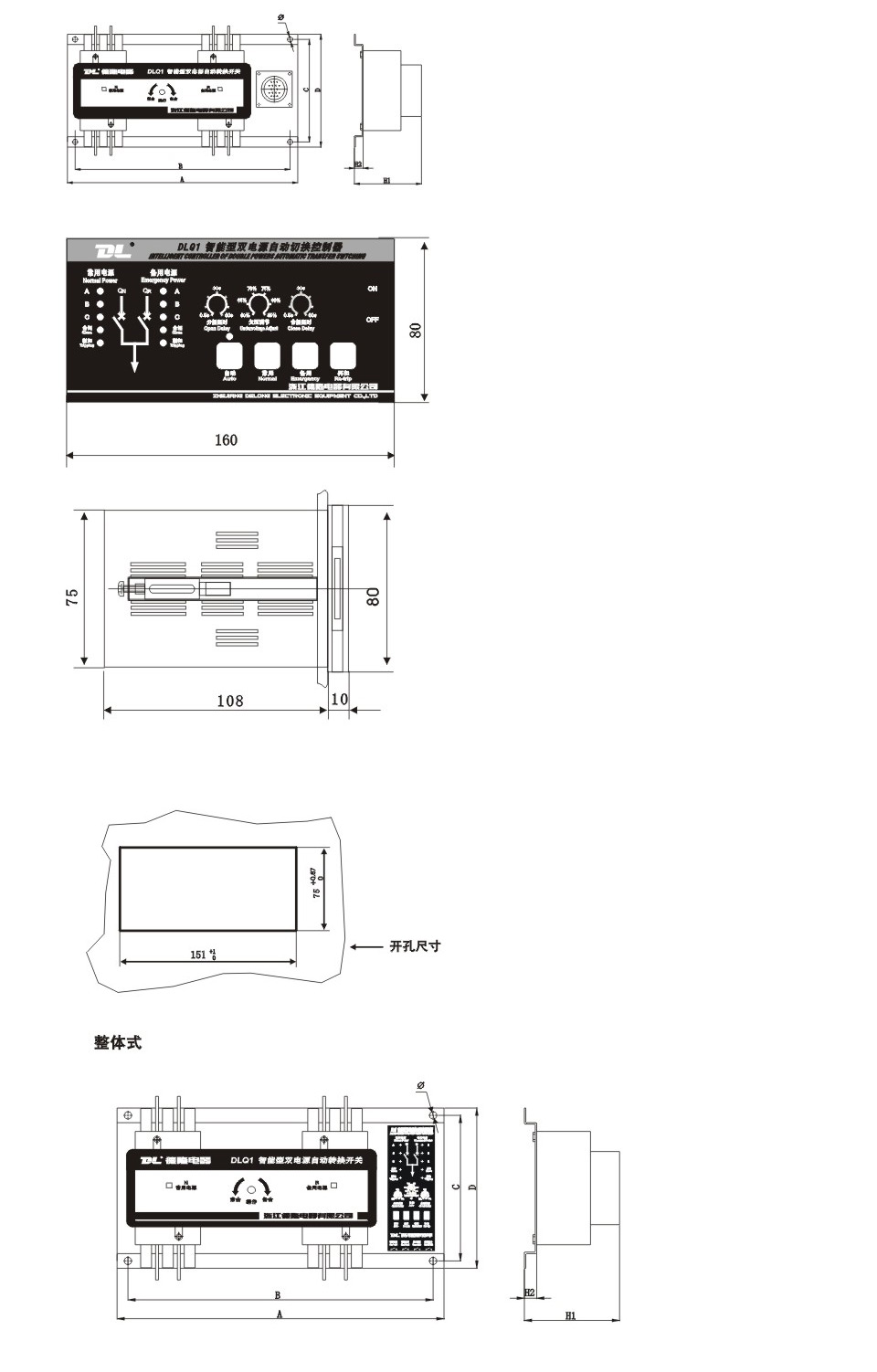
Dimensions and mounting dimensions (see Table 3)
|
Type
|
A
|
B
|
C
|
D
|
H1
|
H2
|
φ
|
|
Level 3
|
Level 4
|
Level 3
|
Level 4
|
|
DLQ1-63
|
460
|
490
|
430
|
460
|
200
|
220
|
170
|
30
|
8.5
|
|
DLQ1-100
|
460
|
490
|
430
|
460
|
200
|
220
|
170
|
30
|
8.5
|
|
DLQ1225
|
475
|
510
|
445
|
480
|
220
|
240
|
200
|
30
|
8.5
|
|
DLQ1-400
|
600
|
640
|
580
|
620
|
300
|
320
|
300
|
40
|
10.5
|
|
DLQ1-630
|
780
|
830
|
760
|
810
|
330
|
350
|
300
|
40
|
10.5
|
|
DLQ1-800
|
780
|
830
|
760
|
810
|
330
|
350
|
300
|
40
|
10.5
|
六、 main structure and working principle
The ATSE automatic transfer switch consists of a two-sided three-pole plastic case circuit breaker and accessories, a mechanical interlocking electric mechanism, an intelligent controller and accessories, and all devices are mounted on a metal base plate. The controller uses MOTOROLA microcontroller and advanced and reliable electronic components to form an intelligent automatic control circuit. The working principle of the intelligent controller is briefly described as follows:
The intelligent controller simultaneously detects the three-phase voltages (rated working voltage 220v) of the common power supply and standby power supply. When the judgment result exceeds 115% Ue of the rated value and the processing result passes the delay, the corresponding command relay is driven to the electric operation mechanism. Issue opening and closing instructions. The above detection results are simultaneously displayed on the panel with 10 light emitting diodes. Through the four touch buttons on the face, two delay adjustment potentiometers can be set to four operating modes ("automatic", "common power", "backup power", "re-buckle"), conversion delay time and Undervoltage value.
The detection and control functions of the intelligent controller are as follows:
Self-resetting intelligent controller (R type)
ATSE is used for automatic conversion between common power supply and standby power supply. Normally, it is powered by a common power supply. When an abnormality occurs in a common power supply (any phase voltage is overvoltage, undervoltage, or phase failure), it is switched to the standby power supply with appropriate delay. When the normal power supply returns to normal, it automatically returns to the normal power supply. When any power fails, the corresponding LED on the panel of the intelligent controller blinks (overvoltage flash frequency 10Hz, undervoltage flash frequency 2Hz) or extinguish (phase loss) to indicate the fault type. The standby power supply must be normally intact. When the backup power supply is abnormal, the intelligent controller sends an alarm signal to the outside (the alarm signal terminal outputs a closing signal) to remind the user to repair immediately.
The function of self-recovering intelligent controller is shown in Table 4
|
Common power supply
|
backup power
|
control function
|
|
normal
|
normal
|
Common power supply: QN, QR
|
|
normal
|
abnormal
|
Common power supply: ON, QR points, send standby fault alarm signal
|
|
abnormal
|
normal
|
After delaying Q1 by t1, and after the delay of t2, QR is combined and the standby power supply
|
|
Back to normal
|
normal
|
The QR is delayed by t1, and then ON after t2 delay, automatically restores to the common power supply
|
The main structure and working principle
Note: ON-common power: (grid power)
QR-backup power supply: (grid power supply)
Tl - opening delay, 0.5-60s (factory setting 0.5s);
T2-break delay, 0.5-60s (factory setting 0.5s);
Self-relying intelligent controller (S type)
ATSE is used for automatic conversion between common power supply and standby power supply. Normally, it is powered by a common power supply. When an abnormality occurs in a common power supply (any phase voltage is overvoltage, undervoltage, or phase failure), it is switched to the standby power supply with appropriate delay. When the normal power supply returns to normal, it does not automatically return to the usual power supply. Unless the backup power supply is abnormal, it can be switched. When any power fails, the corresponding LED on the panel of the intelligent controller blinks (overvoltage flash frequency 10Hz, undervoltage flash frequency 2Hz) or extinguish (phase loss) to indicate the fault type. The standby power supply must be normally intact. When the backup power supply is abnormal, the intelligent controller sends an alarm signal to the outside (the alarm signal terminal outputs a closing signal) to remind the user to repair immediately.
The function of self-relying intelligent controller is shown in Table 5
|
Common power supply
|
backup power
|
control function
|
|
normal
|
normal
|
Common power supply: QN, QR
|
|
normal
|
abnormal
|
Common power supply: ON, QR points, send standby fault alarm signal
|
|
abnormal
|
normal
|
After delaying Q1 by t1, and after the delay of t2, QR is combined and the standby power supply
|
|
Back to normal
|
normal
|
Still using standby power: QR and QN points
|
|
normal
|
abnormal
|
The QR is delayed by t1, and then ON after t2 delay, automatically restores to the common power supply
|
Note: ON-common power: (grid power)
QR-backup power supply: (grid power supply)
Tl - opening delay, 0.5-60s (factory setting 0.5s);
T2-break delay, 0.5-60s (factory setting 0.5s);
The main structure and working principle
Grid-generator intelligent controller (F type)
ATSE is used for the automatic conversion between grid-generator two-way power supply, which is usually powered by a common power supply. When the common power supply is abnormal (any phase voltage overvoltage, undervoltage, phase failure), only the controller can issue control commands. (The power generation control terminal outputs the closing signal) to request power generation and issue an unloading command. (When the generator power generation capacity is not enough, the user selects to unload part of the non-essential load and unloads the command terminal to output the closing signal.) When Duang power generation voltage reaches 85% Ue, it automatically switches to grid power supply with a certain delay; when the normal power supply returns to normal, it automatically returns to the common power supply, and the colleague issues a loading and unloading instruction; (Unloading instruction terminal output disconnect signal ).
The function of the grid-generator intelligent controller is shown in Table 6.
|
Common power supply
|
backup power
|
control function
|
|
normal
|
Not generating electricity
|
Grid power supply: QN, QR
|
|
normal
|
Power generation
|
Power generation request instructions, request power generation
|
|
abnormal
|
Normal power generation
|
After the power generation voltage reaches 85% or more of the rated voltage, the QN is delayed after t1, and an unloading instruction is issued at the same time, the secondary load is unloaded, and QR power is supplied after the delay of t2.
|
|
Back to normal
|
Not generating electricity
|
After delayed by QR QR, and then ON after t2 delay, it returns to the power supply of the grid and issues the loading and unloading instructions at the same time.
|
Note: ON-common power: (grid power)
QR-backup power supply: (grid power supply)
Tl - opening delay, 0.5-60s (factory setting 0.5s);
T2-break delay, 0.5-60s (factory setting 0.5s);
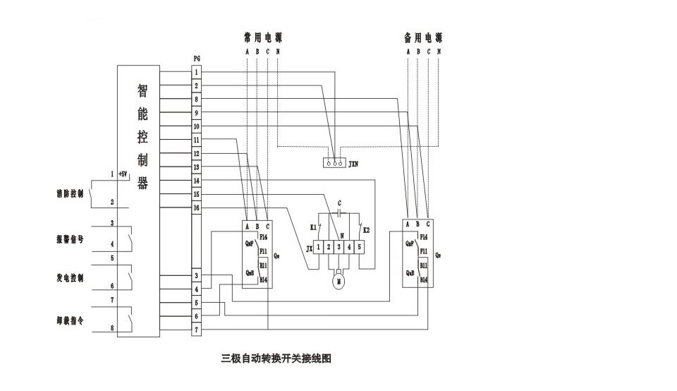
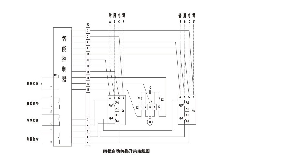
七、secondary circuit wiring diagram
Note: This figure is at the demerit
1.QN: common power circuit breaker 2. Alarm signal for R, S type
QR: Backup Power Circuit Breaker Generation Control, Unloading for Type F
QNF, QRF: Auxiliary contacts of the circuit breaker 3.N must be connected, otherwise it will only damage the controller
ONB, ORB: Alarm contacts of the circuit breaker 4. The dashed line is connected by the user and the rest are connected.
M: operating motor
PG: Cable Connector
JX1, JX2: Terminal Block AZ4-1006
JXN: N pole terminal
Note: This figure is at the demerit
1.QN: common power circuit breaker 2. Alarm signal for R, S type
QR: Backup Power Circuit Breaker Generation Control, Unloading for Type F
(This figure is at the demeriting position again)
QNF, QRF: auxiliary contacts of the circuit breaker 3.N Neutral cable must be connected, otherwise it will only damage the controller
ONB, ORB: Alarm contacts of the circuit breaker 4. The dashed line is connected by the user and the rest are connected.
M: operating motor
PG: Cable Connector
JX: Terminal Block AZ4-1006
 八、installation and adjustment
In order to ensure your personal safety and the safety of electrical equipment, before ATS puts it into operation, users must ensure that:
ATSE must read the instruction manual carefully before installation and use;
ATSE must be put into use under normal working conditions;
Check whether the specifications of the ATSE circuit breaker meet the requirements before installation.
Measure the insulation resistance of the main circuit before and after installation with a 500V optical ohmmeter (please note: the secondary circuit must be disconnected, otherwise the intelligent controller will be damaged). The ambient temperature is 20°C±5°C and the relative temperature is 50%-70%. Should not be less than 10MΩ. Otherwise the circuit breaker must be dried before the insulation resistance reaches the specified requirementsuse.
When installing, ATSE installation distance should meet the safety distance requirements.
Do not let foreign objects fall into the product during installation.
When installing, the connecting wire should be entrained with no mechanical stress on the circuit breaker to avoid affecting the operating characteristics.
After the product is installed, the conductor cross section that meets the standard should be selected according to the rated current. For four-pole circuit breakers. The N line should not be wrong, otherwise it will burn out the intelligent controller and the motor operating mechanism. For the three poles, an additional N pole wire must be added to the terminals of the product.
When installing the product, the cable connector of the intelligent controller should be plugged in the direction shown in the figure. Otherwise, the intelligent controller will be burned out and cannot be used normally.
Split Intelligent Controller cable length is 18 meters.
Note: The phase sequence of the two circuit breaker input terminals must be the same, and the product's protective grounding should be reliable.
九、 manual control debugging (in order to self-investment and recovery as an example)
Switch on the power supply of the common power supply, standby power supply, and intelligent controller. At this time, the indicator above the “auto” button on the controller panel is flashing, and the six electrical indicators A, B, and C appear bright, indicating the intelligent controller. In the automatic control state, it is detected that the six-phase voltage is normal. If one of the indicators is off or flashing, the corresponding phase of the power supply is missing phase, overvoltage (blink frequency IOHz) or undervoltage (flash frequency 2Hz).
Click the "Auto" button, the indicator light above the "Auto" button on the controller panel goes out, and the controller is under manual control.
After confirming that the power is normal, press the "common power" button, the QN circuit breaker closes, press the "backup power" button, the QN circuit breaker opens and closes, the QR circuit breaker closes, and then click the "common power" button, QR The breaker is opened and the QN breaker is closed.
Press the "Re-drag" button. If there is a circuit breaker in the closing position before the power is on, the circuit breaker is opened. If the circuit breaker is in a tripped state, it is "re-buckled".
Click the "Auto" button, the indicator above the "Auto" button will flash, the controller will enter the automatic control state, and the controller will work normally.
When the mind wants, it can also be used as a test of the release lamp, that is, the panel cover of the ATSE is opened after the circuit breaker is closed, the trip button of the circuit breaker is pressed, and the trip alarm indicator on the intelligent controller after the circuit breaker is tripped. Should be lit, and then the indicator light goes out after the buckle.
Note that when a circuit breaker trips, the function on the controller must be switched to the manual mode. After the circuit fault is removed, the "Re-buckle" button is operated to make the tripped circuit breaker de-energized before it can be switched to The automatic state closes the circuit breaker.
十、Fire control signals
ATSE has a pair of external normally open contacts to provide users with fire control signals. When a fire occurs, the fire control center gives a control signal to the intelligent controller. At this time, the two circuit breakers enter the open state and cut off the power of the load terminal. . When the fire signal fails to resolve, both the normal power supply and the standby power circuit breaker of the automatic transfer switch cannot be closed in either the “manual” or “automatic” state. Only after the fire control signal is removed, the switch is automatically converted to normal power supply.
十一、use method
After the above test, the working ATSE system can be put into use. Before it is put into use, which power source is selected (that is, the button of the power source is clicked on), then the “Auto” button is in the “Auto” state, and the panel is automatically The indicator lights up so that the entire ATSE enters automatic control.
十二、 Failure Analysis and Troubleshooting
After start-up, there is no response. After the instruction button is pressed, the mechanical interlock transmission mechanism does not operate. Please check the power supply and connection line of the disconnector. The three-phase power supply and the neutral line must be connected properly, and the connector on the intelligent controller should be firmly fixed. Good contact.
After the power is turned on, the controller has power, but the mechanical interlocking drive does not operate. Check whether the fuse tube on the intelligent controller is blown due to the current of the electric operating mechanism is too large. Then replace the fuse with a 3A fuse and try again.
Regularly burn the fuse tube, check whether the interlock mechanism of the mechanism is stuck, and try again after proper adjustment.
The periodic inspection and maintenance shall be based on the requirements of the circuit breaker and mechanical interlock transmission mechanism selected later.
If it is required to perform power frequency voltage withstand test on the ATSE, please disengage the intelligent controller.
When the ATSE is in overhaul or periodic inspection, please use manual debugging.
Products that are not used for a long period of time should be protected against moisture and dust, and they should be commissioned as described above before use, and they can be put into operation after normal operation.
If you have special requirements, please contact the manufacturer and specify when ordering.
This product is guaranteed for one year from the date of delivery. During the warranty period, the user adjusts, uses and maintains the product according to the requirements of the product. However, if the product cannot be used due to quality problems, the factory is responsible for repair, replacement, or return.
十三、ordering instructions
Automatic transfer switch ordering should indicate the product model shell frame level power supply and rated current, controller control method, number of poles, structure type and number of units.
Example: Order DLQI, 160A shell-level power supply, 80A rated current, 100 self-repairing R-type, 4-pole split type products, with DLQ1-160R/80/4F 100 units.
You can also click "Order" to fill in the contents.
|
product code
|
囗100 囗125 囗160 囗250 囗400 囗630 囗800
|
|
Frame level current(A)
|
囗RSelf-reconstituted 囗SSelf-relying 囗FGrid - Power Generation
|
|
control method
|
囗10 囗15 囗16 囗20 囗25 囗32 囗40 囗50 囗60 囗80
囗100 囗125囗160囗200囗250囗315囗400囗500囗630囗800
|
|
Rated current(A)
|
囗3pole 囗4pole
|
|
Number of poles
|
囗FSplit type 囗ZIntegral
|
|
structure type
|
|
|
Ordering unit (official seal)
|
|
|
Contacts
|
|
Tel
|
|
|
Fax
|
|
number
|
|
|
Note
|
|